Photos
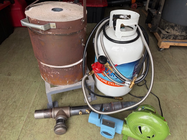
The furnace is propane-fired and sized to accommodate a No. 8 crucible, allowing melts of approximately 8 lbs of aluminum or around 20 lbs of brass, bronze, or gray iron.
The furnace is built in three main sections: a bottom, a body, and a lid. The lid is mounted on a swivel mechanism and lifted via a foot-operated pedal, allowing it to be easily raised and rotated clear of the opening for access to the crucible.
Lastly, a welded steel frame supports the furnace and lifting mechanism.
Gingery’s design also suggests a lifting mechanism for the main body to access the crucible. While I invested considerable effort in building this feature, it ultimately did not perform as intended and was abandoned. Instead, I fabricated a set of lifting tongs to remove the crucible directly from the furnace—a much simpler and more reliable solution that worked well in practice.
Combustion air is supplied by a blower (green). Initially, the airflow was too strong and tended to blow out the flame, so I designed and 3D printed an adjustable air regulator (blue). This unit incorporates shutters (black) to control how much air is directed into the furnace versus bypassed out an exhaust port.
The regulated air is then fed into a mixing tube (black), where propane is introduced through a brass fitting. A regulator (red) controls the propane flow, allowing the air-fuel mixture to be tuned for stable and efficient combustion.
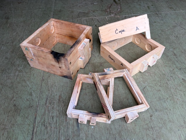
The process starts with making a pattern of the desired part. Patterns are typically split into two halves so they can be removed cleanly from the sand. Vertical surfaces need a bit of draft (a slight taper) to help release the pattern, and all edges are radiused to prevent the sand from breaking down at sharp corners.
To begin molding, one half of the pattern is placed face down on a flat surface inside the drag, which is the bottom half of the mold box. A light dusting of parting compound is applied so the sand won’t stick to the pattern. Molding sand is then packed firmly around it.
Next, the drag is flipped over, and the second half of the pattern is set in place, aligned using dowel pins. More parting dust is applied, and the cope—the top half of the mold box—is positioned on top. Sand is again packed in, completing the mold.
Once the sand is compacted, the cope and drag are separated and the pattern is carefully removed, leaving behind a clean impression of the part. If the design requires internal features, cores are set into place at this stage. The gating system—sprue, runners, and gates—is then cut into the mold to guide the flow of metal.
Alignment pins built into the mold boxes ensure the cope and drag register properly when reassembled. At this point, the mold is ready for pouring.
One practical note from experience: it’s important to keep the cope and drag firmly clamped or weighted together during the pour. Molten metal exerts quite a bit of force, and if the halves lift even slightly, it will find its way out—usually in a hurry. Ask me how I know… the tender pump casting provided a memorable reminder.
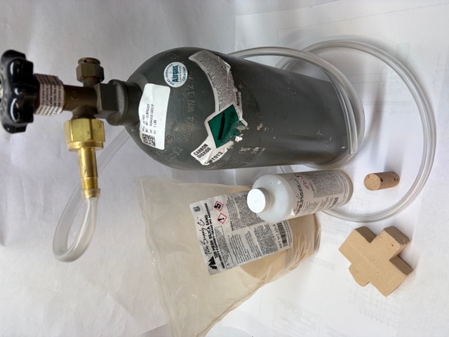
Making a core is a fairly straightforward process. Fine-grained sand is mixed with sodium silicate to form a thick, moldable putty. This mixture is then packed into a core box (a mold for the core itself), making sure it’s well compacted and fully fills the shape.
Once formed, the core is exposed to carbon dioxide gas, which reacts with the sodium silicate and quickly hardens the mixture. In the shop, a simple and effective method is to place the filled core box into a large Ziploc bag and introduce CO₂ into the bag. It doesn’t take long—typically about a minute of exposure is enough to fully set the core.
Two examples are shown here. The cylindrical core is used to form the bore of the tender pump, while the other is shaped for the swing bolster on the leading truck of a Northern locomotive.
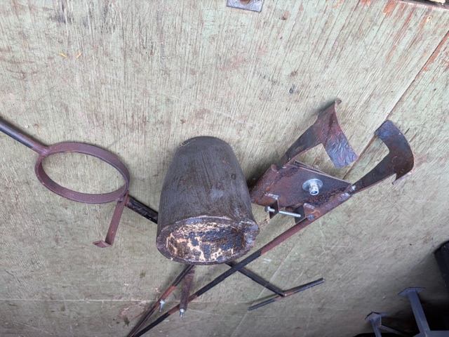
To the left are the lifting tongs, used to remove the crucible from the furnace once the metal is up to temperature. At that point, things get serious—everything is hot, and often heavier than you’d like.
On the right is the pouring ring. The hot crucible is set into this ring for the actual pour. The vertical tab slides on the pouring handle and hooks over the lip of the crucible, keeping it securely captured as it’s tilted. It’s a simple but critical detail—it prevents the crucible from shifting or falling out of the pouring ring.
It pays to rehearse the sequence ahead of time, making sure everything is staged and within easy reach. The mold boxes, pouring ring, and ingot molds (for any leftover metal) should all be positioned and ready before the crucible comes out of the furnace.
All of these tools were made from steel bar stock and welded together using a flux-core welder. They are essential for a safe, successful pour.
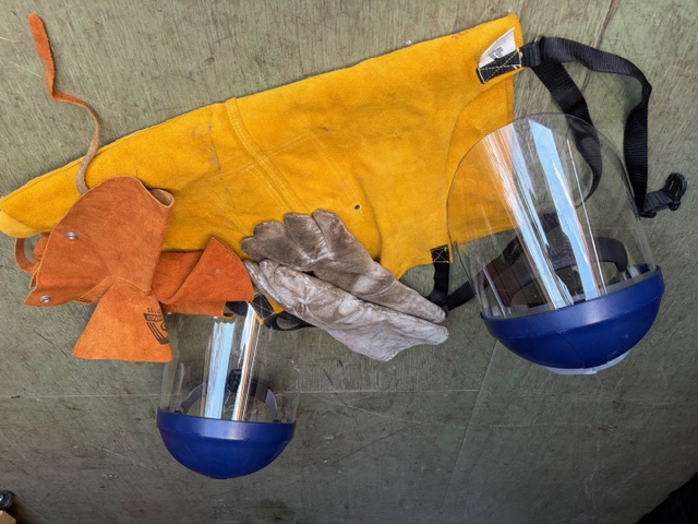
One point that can’t be overstated—everything in the process must be completely dry. Any moisture in the metal, molds, or tools can flash to steam instantly when it contacts molten metal, expanding violently and ejecting metal in all directions. Not good. Be safe.